CFD simulations involving 3D complex geometry have become the norm, however, this hasn’t lessened the…
Twin box bridge deck meshing
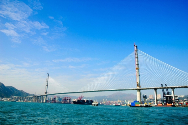
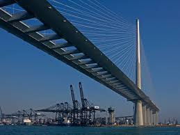
Applied CCM are the distributors of Pointwise in Australia and New Zealand. This is the second in a series of meshing articles you will see from us in 2019. February’s mesh showcases twin-box decks of a bridge on a Pointwise mesh. Examples of bridges that adopt twin-box deck arrangements are: Yi Sun-sin suspension bridge located in South Korea, the Xihoumen suspension bridge located in China, and the Stonecutters cable-stayed bridge situated in Hong Kong.
Further understanding of the aerodynamics and aeroelastic performance under a wide range of scenarios, suppress the vortex-induced vibration (VIV) while increasing the efficiencies of the flutter response. A high quality mesh is critical to perform an aerodynamic analysis with computational fluid dynamics (CFD).
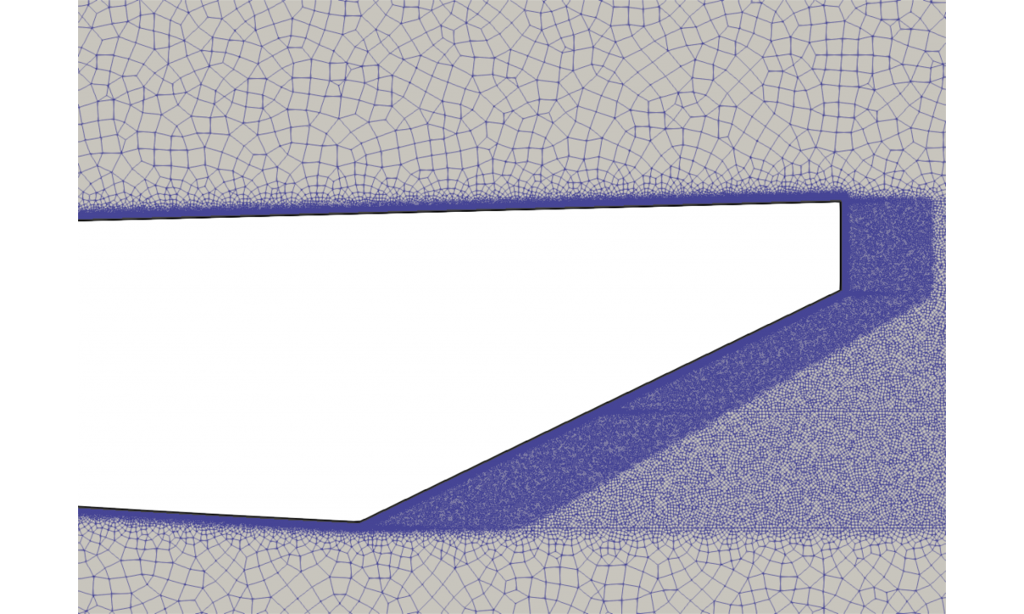
The computational domain (shown in Figure 1) is subdivided into 3 different zones. The first zone closest to the boxes, is the buffer zone. Care was taken to obtain a high-density mesh, in the gap between decks.
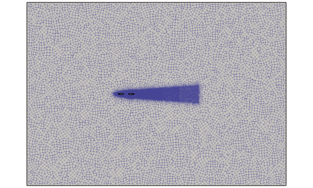
Zone 2, a strip downwind of the buffer zone, termed the wake zone. The evolution of vortices shed from the deck dissipates as they drift away (Figures 2 and 3).
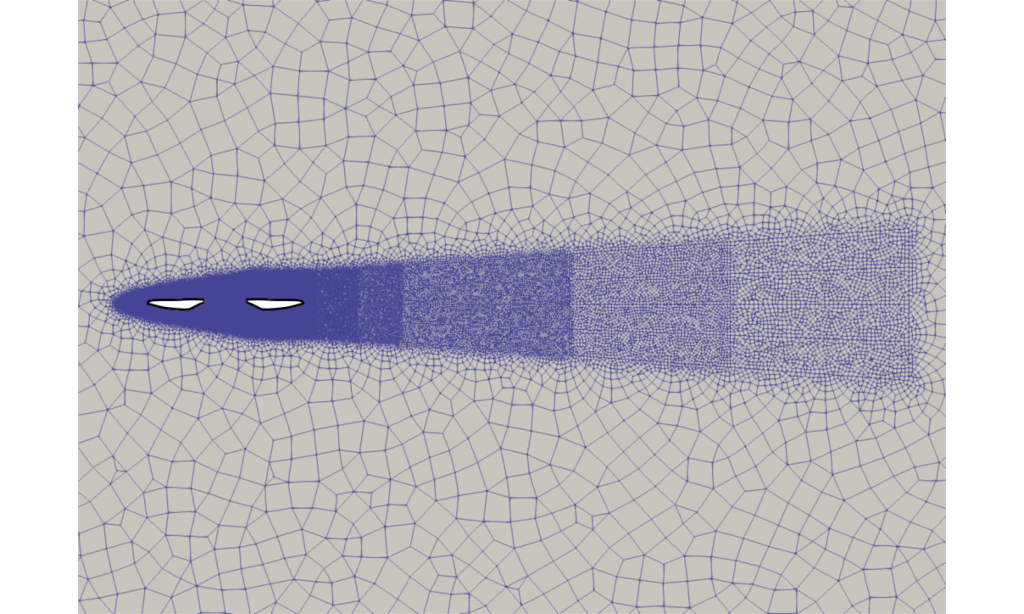
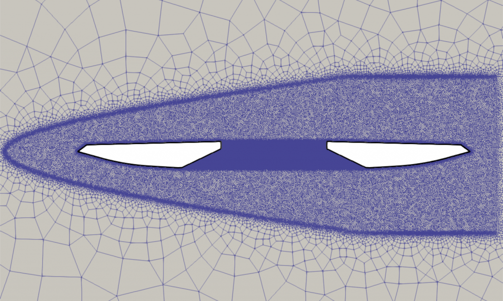
The far-field zone represents the overall size of the fluid domain. This was sufficient to avoid the influence of boundaries on the solution. Except for the boundary layer region, an unstructured quadrilateral grid was locally defined and orthogonality was employed. This region utilised a structured quadrilateral structured mesh (Figures 4-6).


Check out last month’s mesh if you missed it!
Thanks for reading, the next edition will be March 2019. Until then, happy meshing!
For a free trial of Pointwise, go here.
This work was undertaken by Dr. Robert Ong, of Applied CCM.
Related Posts

2.
Twin box bridge deck meshing