AFMC (Australasian Fluid Mechanics Conference) is held biannually in Australia, and the 22nd AFMC2020 was…
2D Sources in Meshes in Pointwise 18.4R1
CFD simulations involving 3D complex geometry have become the norm, however, this hasn’t lessened the need for 2D simulations. Sometimes geometry and flow are such that a 2D simulation is the most appropriate approach.
2D meshing
In versions of Pointwise prior to 18.4R1, only blocks and domains within a block would be influenced by source regions. In order to export a 2D mesh from a Pointwise domain, a sacrificial block of nominal thickness was needed to produce a domain with source refinement. A new feature of Pointwise in version 18.4R1 is the ability to use “sources” for refinement of domains. The domain’s isotropic triangles and quads can now be influenced by source regions, without the need for a block.
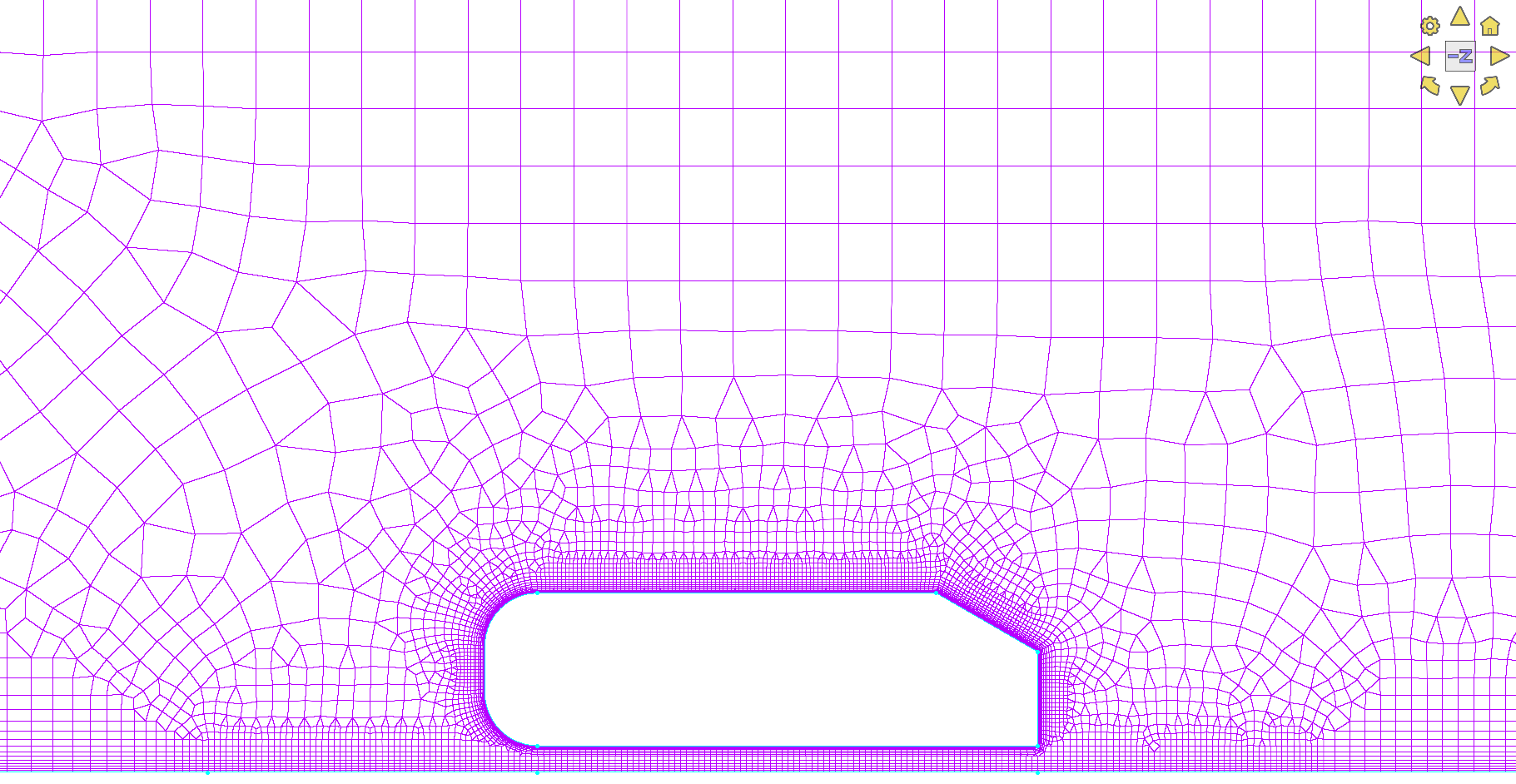
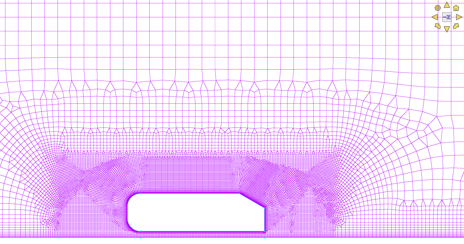
In this article, the 2D Ahmed-body that was previously discussed in our 2D meshing with sources in Pointwise article is used. We start with a 2D mesh around the Ahmed body as Shown in Figure 1.
Mesh adaption with sources
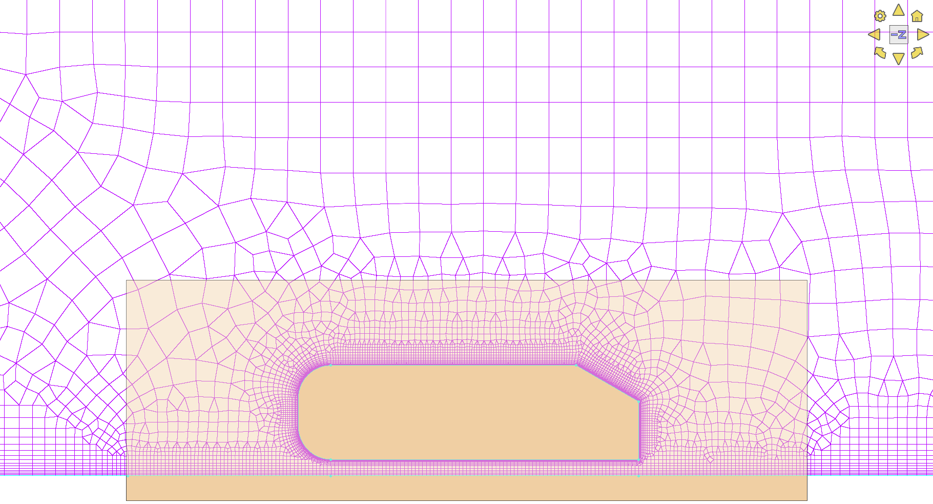
The next step is to create the source region we want to influence the mesh. Figure 2 shows a single rectangular region covering the Ahmed body. Pointwise has options for several common shapes such as box, cylinder, and sphere as well as an arbitrary polygon shape.
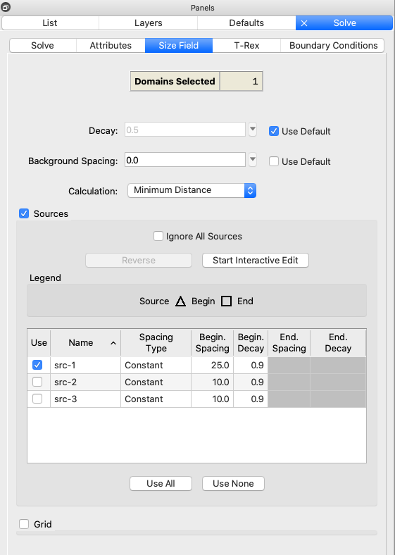
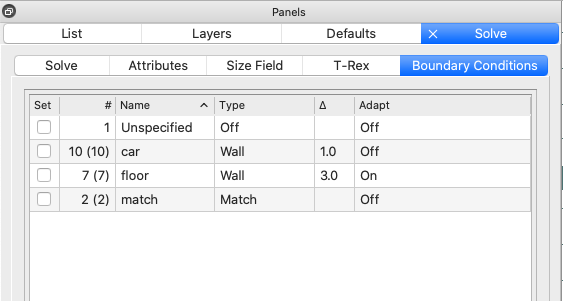
The effect of the source region on the mesh is controlled through the Size Field tab within the Grid Solve command. Figure 3 shows an example of the Size Field tab with the selection of one source region (src-1). The Boundary Conditions tab (Figure 4) allows you to specify how each bounding connector of a domain will be treated when using the solver. The last column in the boundary condition table is the Adapt column. By default, this option will be set to Off. When set to On, connectors assigned to the corresponding boundary condition will have their point clustering adapted, points added or removed, in order to meet the target cell sizes specified by any selected size field influencers on the Size Field tab.
Upon initialisation, the cell sizes in the mesh and connector spacings will be influenced by the source region spacings and decay values as shown in Figure 5. That’s all that is required to include source region influence on a 2D mesh.
Exporting the mesh as 2D
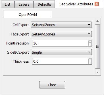
The last step is to export the mesh as 2D. For OpenFOAM, 2D meshes will be extruded by one cell thick upon export. Users have the option of specifying the extrude distance or having Pointwise calculate the distance as an average of the cell edge length (see Figure 6, solver attributes panel). Allocate the edges of the mesh to boundary conditions. Lastly, choose File -> Export -> CAE to write out the polyMesh ready for OpenFOAM or Caelus.
CFD results
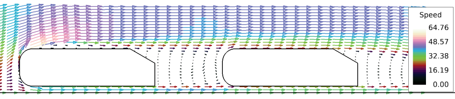
The 2D meshing approach described above was used to simulate tandem Ahmed bodies with a varying separation distance. Figure 7 shows an example mesh when the separation distance was half a body length (0.5L). Simulations were run for air at 35 m/s using Caelus 9.04.
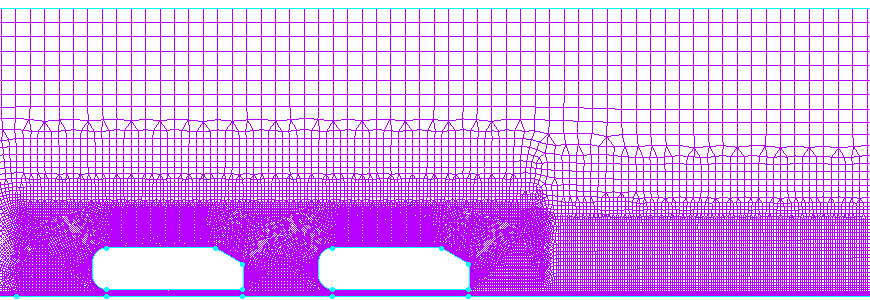
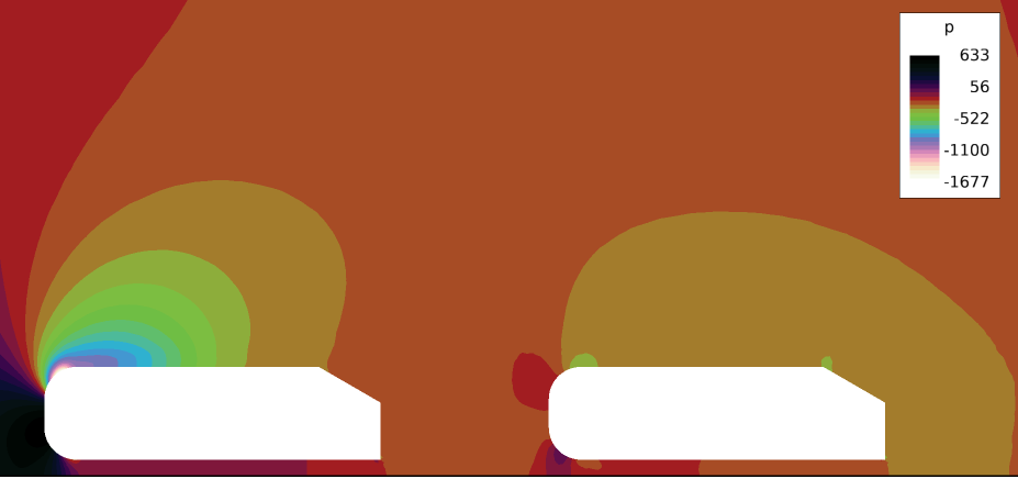
Figure 8 shows the results for the pressure distribution. Whilst Figure 9 shows the velocity results for the separation distance of 0.5L.
To find out more about Pointwise go here, or for a free trial of Pointwise, go here.
Related Posts
21.
2D Sources in Meshes in Pointwise 18.4R1