CFD simulations involving 3D complex geometry have become the norm, however, this hasn’t lessened the…
Pointwise as a Pre-processor for CFD
Introduction
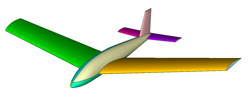
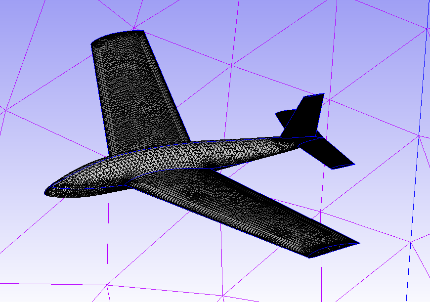
In this month’s blog we use Pointwise as a pre-processor for performing a CFD analysis with ANSYS Fluent and OpenFOAM from the same Pointwise mesh. The geometry (Figure 1) is that of a glider and comes from the examples provided with Pointwise automatic meshing github repo called GeomToMesh.
For OpenFOAM in particular this is handy as OpenFOAM requires text based setup of boundaries conditions types, as well as manually specifying the location of boundary conditions within the boundary file.
The Mesh
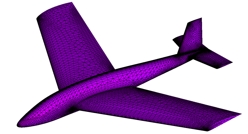
Preparing the geometry (database in Pointwise terminology) for meshing required cleaning up the surface geometry and assembling into quilts: regions that will be meshed with a single surface mesh. The benefit of quilting is that a mesh topology is vastly simpler than the underlying geometry model topology. Finally a watertight database model is created ready for surface meshing (Figure 2) and volume meshing.
Pointwise as a Pre-processor for Fluent
With the surface mesh and volume mesh created, we can see how Pointwise is used to create boundary conditions and volume conditions (zones), for Fluent and OpenFOAM.
Let’s start with Fluent
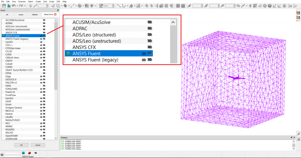
Step 1 – Select Fluent as CAE Solver
Within Pointwise select the solver by going to menu CAE-> Select Solver… and choose Fluent (Figure 3).
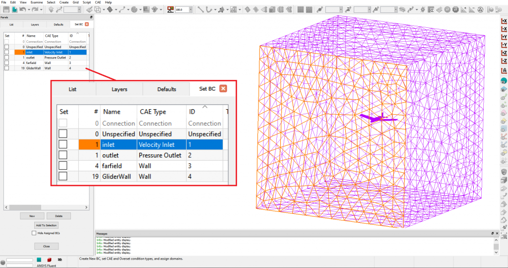
Step 2 – Create and Locate BCs
Create a BC for each boundary condition by clicking New, Select the patch and tick the associated box. Chose CAE types (eg Wall, Pressure Outlet etc) (Figure 4).
Step 3 – Export CAE to a .cas file
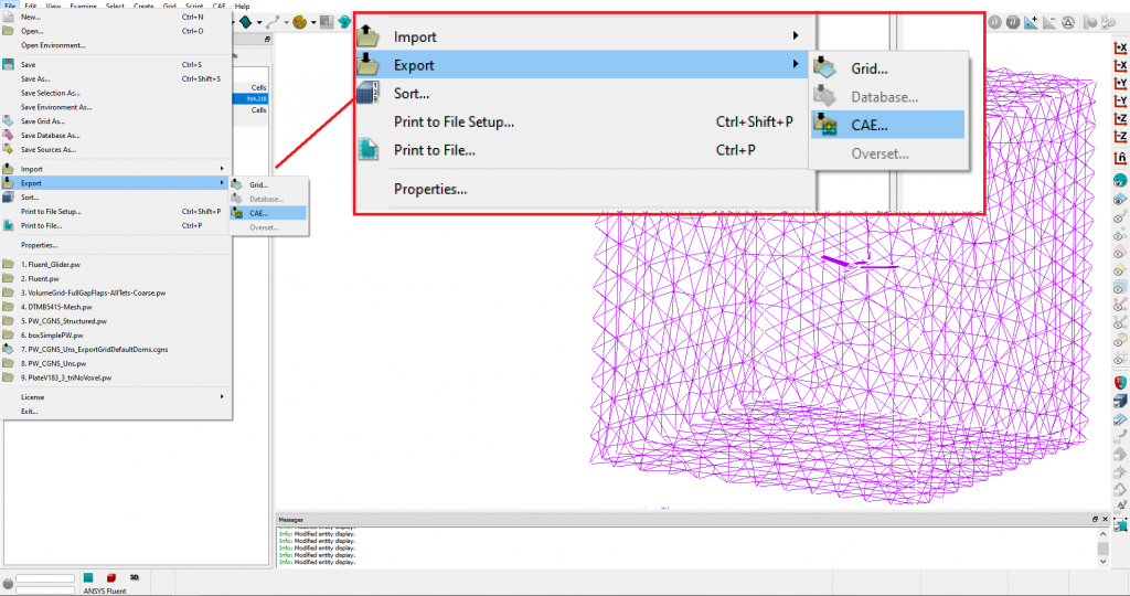
Select the volume blocks and go to menu File -> Export -> CAE and select the name of the cas file to export (Figure 5).
Step 4 – Import CAE to Mesh Fluent and Run
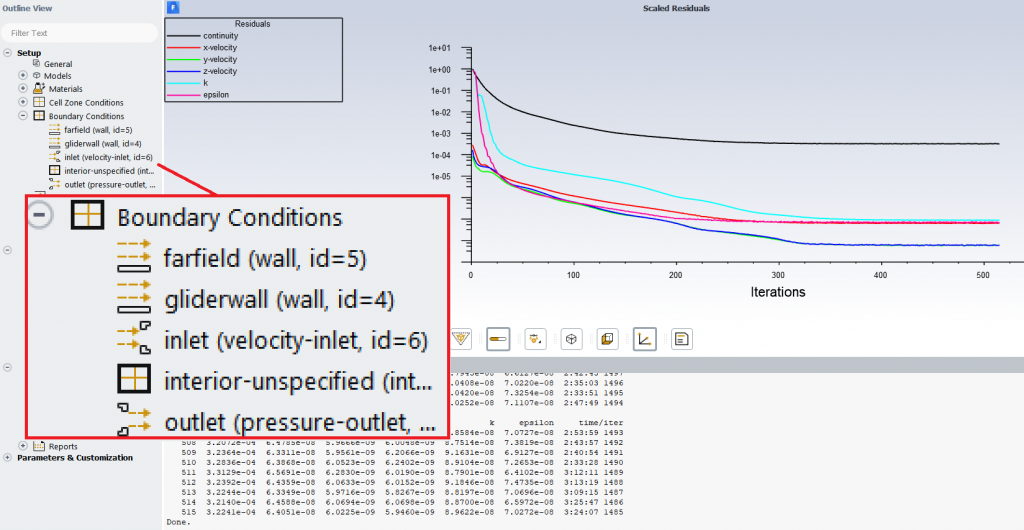
In Fluent import the cas file (which is the mesh), and define the values for the already named inlet and outlet, wall boundary conditions. Also define any other solver settings (Figure 6).
Pointwise as a Pre-processor for OpenFOAM
With the same Pointwise mesh, we can also switch to OpenFOAM as the solver. Then we can change the boundary conditions types to OpenFOAM types.
Step 1 – Select OpenFOAM as the CAE Solver
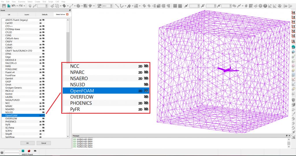
Within Pointwise select the solver by going to menu CAE-> Select Solver… and choose OpenFOAM (Figure 7).
Step 2 – Define and Select OpenFOAM boundary conditions
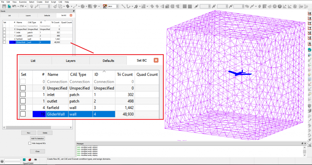
Create a BC for each boundary condition by clicking New, Select the patch and tick the associated box. Chose CAE types (eg Wall, Pressure Outlet etc ) (Figure 8).
Note: if the BCs were setup for another solver the names will remain, and the type of BC will need to be adjusted
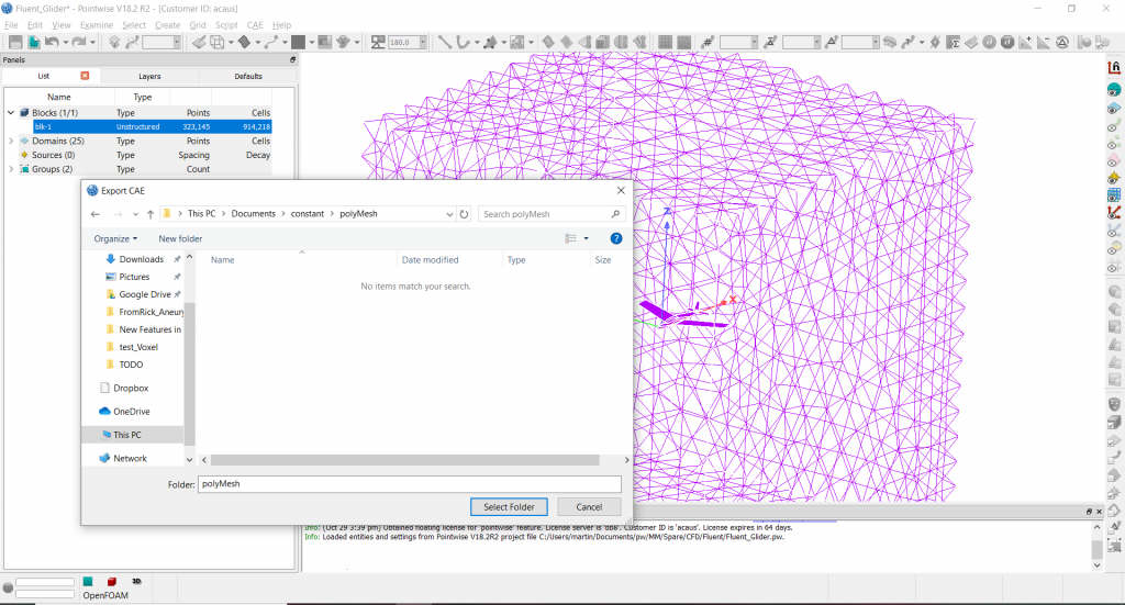
Step 3 – Export CAE to constant/polyMesh
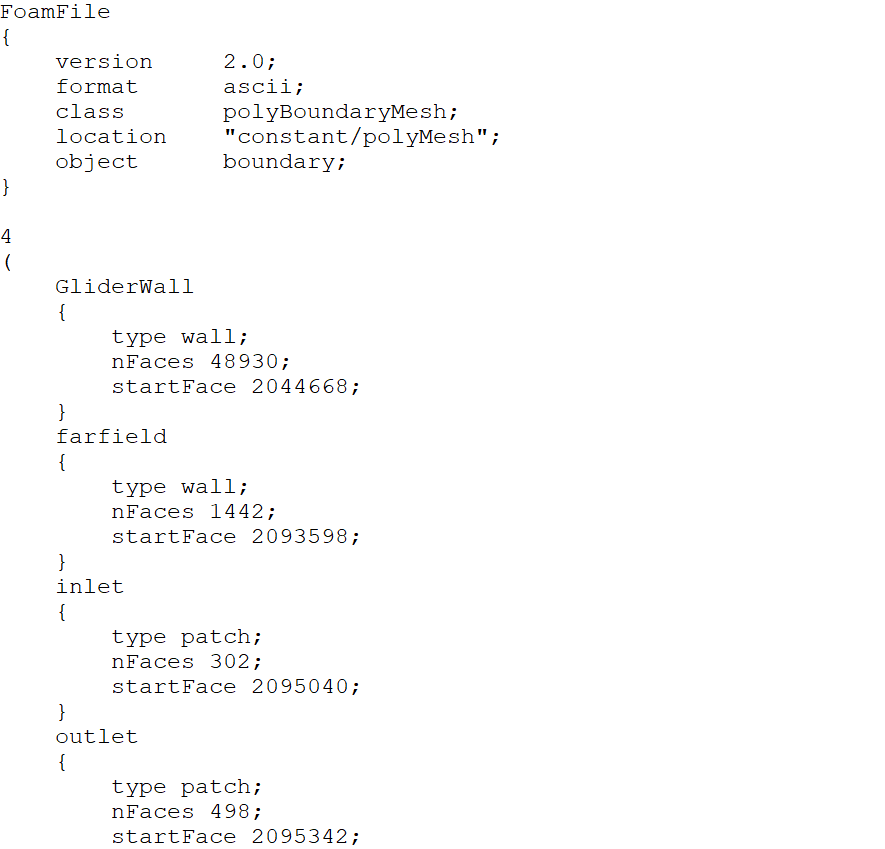
Select the volume blocks and go to menu File -> Export -> CAE and select the constant/polyMesh directory to export (Figure 9). After export, the boundary file will be written with the boundary conditions types and names all set by Pointwise from the earlier specification (see Figure 10).
Thanks for reading, the next edition will be later in November. Until then, happy meshing!
To see more about our Pointwise distribution go here, or for a free trial of Pointwise, go here.
Don’t forget to register for next month’s webcast on Mesh Adaption with Pointwise and Caelus.
Related Posts

10.
Pointwise as a Pre-processor for CFD