CFD simulations involving 3D complex geometry have become the norm, however, this hasn’t lessened the…
Horizontal wind turbine near a bridge
Background
The June mesh showcases the Pointwise meshing and Computational Fluid Dynamics (CFD) analysis of a horizontal wind turbine placed under a twin deck bridge. This case was meshed in February, however we have now added a turbine rotor near one of the two decks, and performed the CFD analysis.
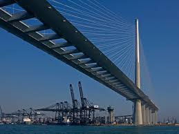
Just to recap, the Stonecutters cable-stayed bridge situated in Hong Kong is shown in Figure 1.
CFD modelling will be performed with Caelus (www.caelus-cml.com) to understand the interaction between the bridge and the horizontal wind turbine. This will aid in understanding of the aerodynamics and ultimately the performance of the turbine. Further studies on the optimal placement of the turbine are then possible.
Pointwise Mesh
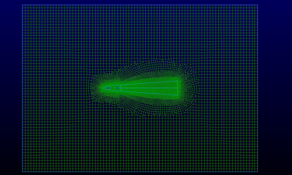
The computational domain is taken as a 2D slice of the actual bridge and turbine, however Caelus requires 3D elements, so a symmetry plane is used in the third dimension. The elements are made up of hexa’s and triangular prisms (shown in Figures 2 -4) and the domain is subdivided into 3 different zones:
1) Far field zone (Figure 2): – boundary inlet and outlets, interfacing with the twin deck zone and make up largely of hexa elements close to perfectly orthogonal and with aspect ratio close to 1.
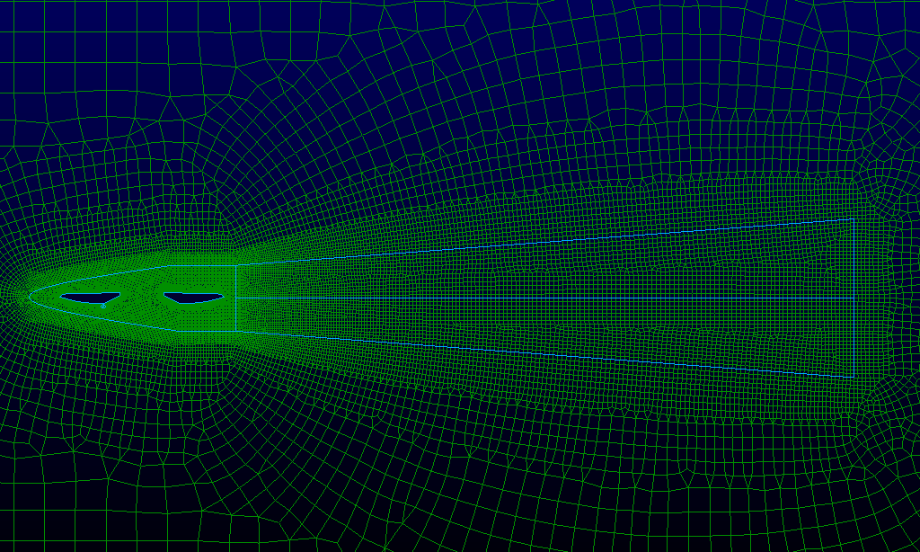
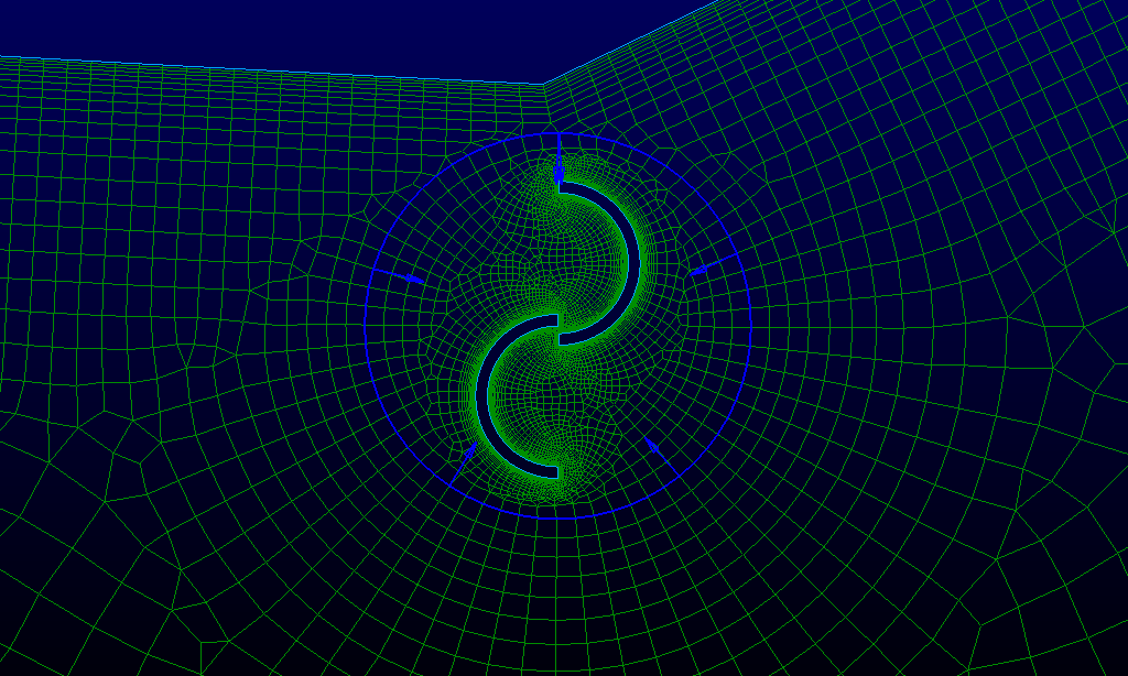
2) Twin deck and wake zone (Figure 3, 4a) : surrounding the twin decks and in the wake downstream, and interfacing with the rotor domain, assigned as a stator (Figure 4a)
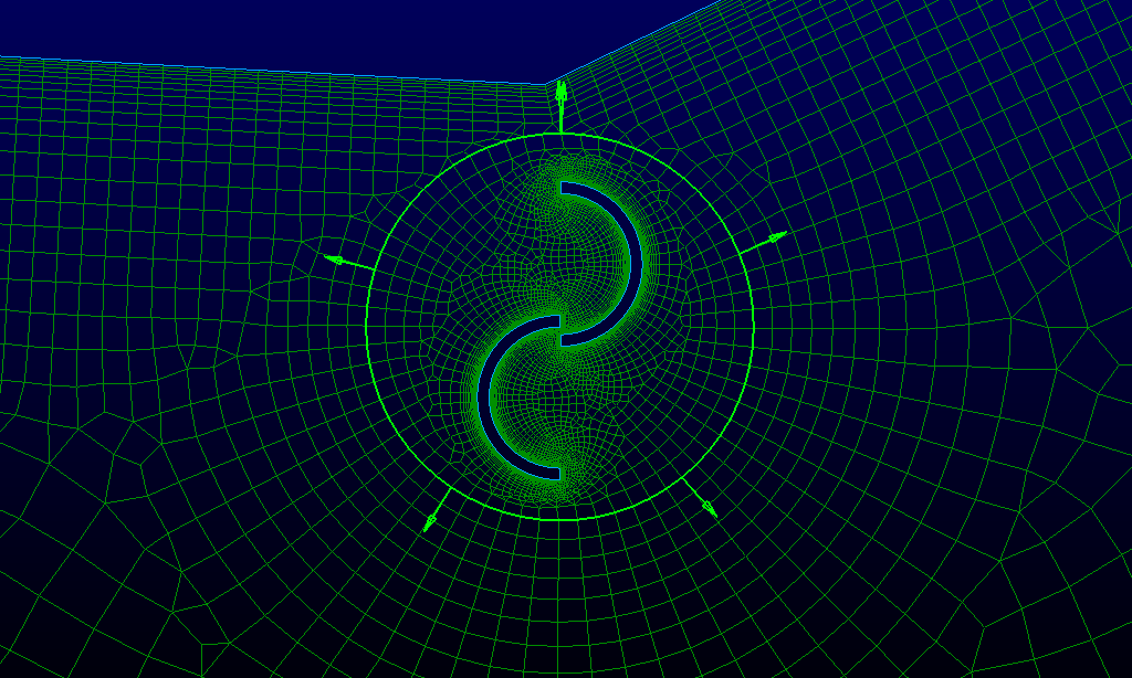
3) Rotor zone (Figure 4b): near the rotor with a zone to allow for the rotating mesh, In Pointwise this zone is assigned as a Volume Zone so that it is able to be assigned as the rotor in a moving mesh.
CFD Analysis
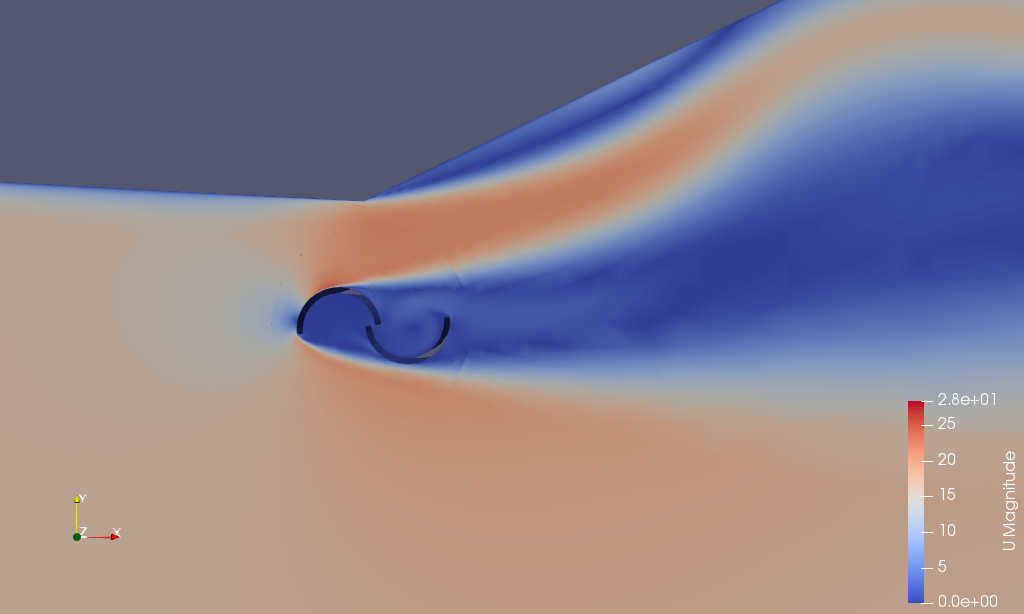
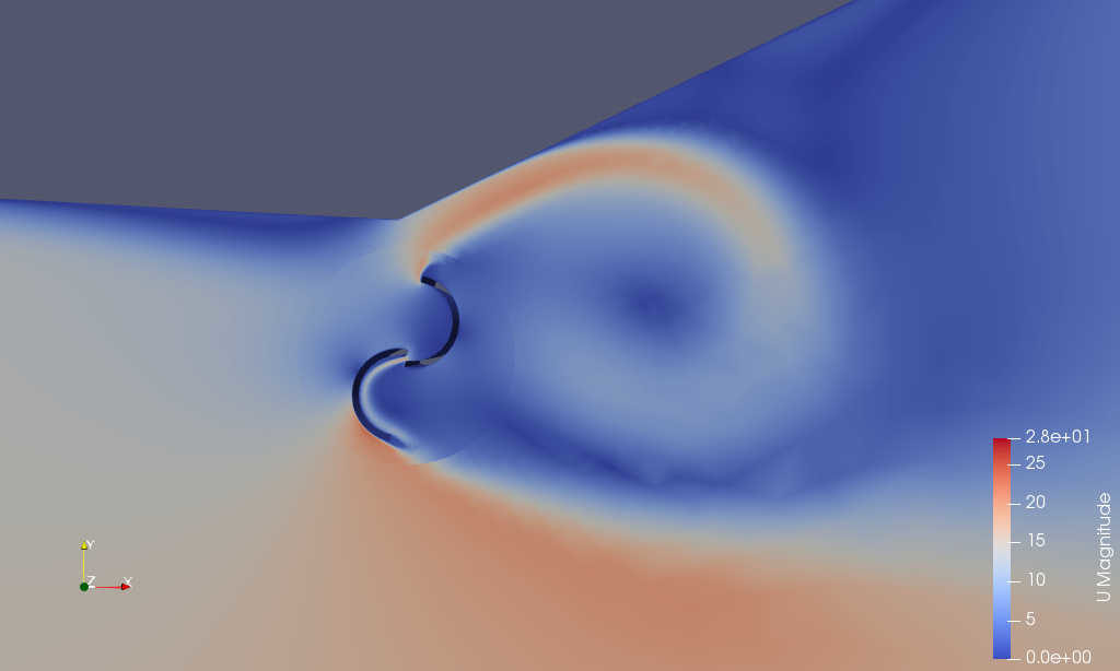
The transient CFD analysis is performed with Caelus using pimpleSolver, with the movement of the rotor modelled using Caelus’s dynamic mesh functionality. Figure 5 and 6 shows two time snapshots of the rotating turbine.
Thanks for reading, the next edition will be later in July 2019. Until then, happy meshing!
For a free trial of Pointwise, go here.
The mesh and CFD analysis was performed by Dr Darrin Stephens and Dr Robert Ong.
Related Posts

6.
Horizontal wind turbine near a bridge