CFD simulations involving 3D complex geometry have become the norm, however, this hasn’t lessened the…
Normal Extrusion Hybrid Meshes for Multi-Element Airfoils
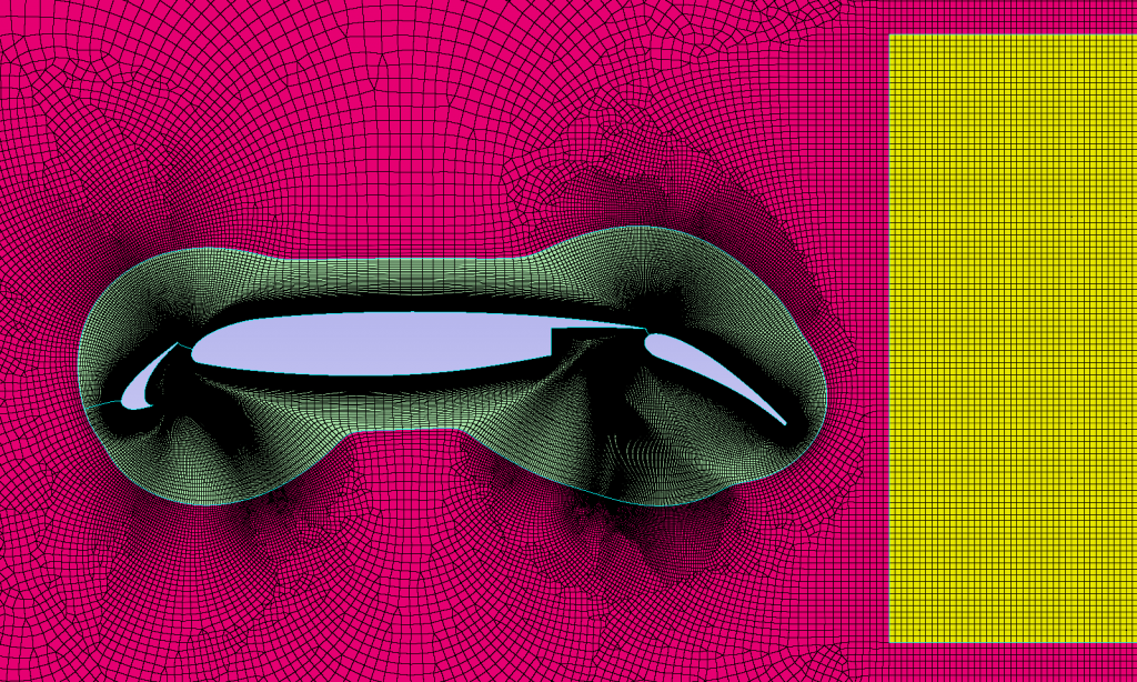
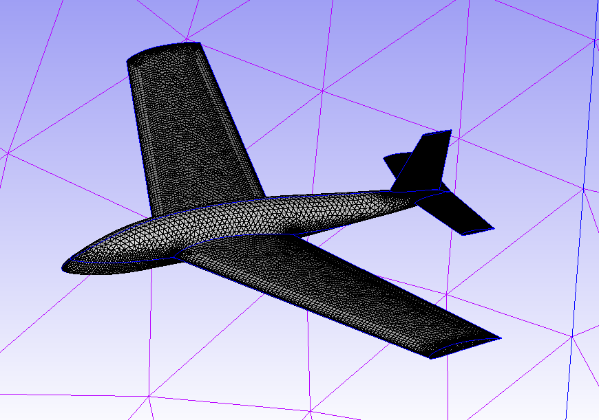
In this monthly mesh, during COVID-19 we continue to focus on Aerospace meshes with Pointwise, whilst working from home. This article steps through how Pointwise can be used to generate normal extrusion hybrid meshes for multi-element airfoils as shown, in Figure 1. The meshing of this airfoil as a 100% normal extrusion shown previously as a video and blog. However, this results in non-planar farfield boundaries at the end of the normal extrusion. Some Computational Fluid Dynamics (CFD) solvers can use Non-planar farfield boundaries. Still, some solvers do not perform well, or cannot run at all with non-planar farfield boundaries. In this blog, the steps involved to create a hybrid mesh made up of a structured normal extrusion domain and a rectangular unstructured domain surrounding the normal extrusion domain. We do this for a multi-element airfoil geometry.
Normal Extrusion for Multi-Element Airfoils
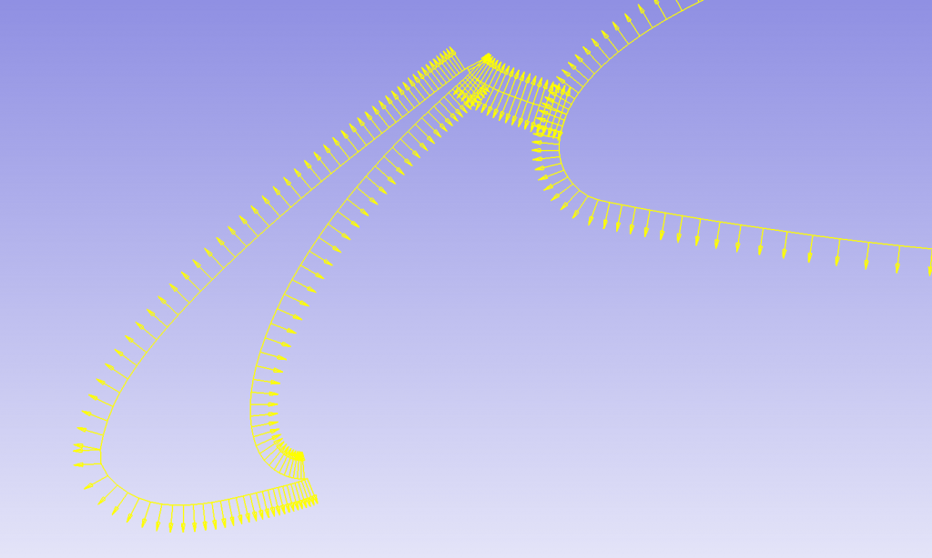
The normal extrusion is a unique feature of Pointwise. This feature allows connectors on the 1D edge to be used as a starting entity for a 2D structured extruded domain. Likewise, the extrusion can also be applied to a 2D domain to form a 3D volume mesh. However we will use the former during this blog. The connectors may represent the cross section of an airfoil, or multiple airfoils. In this blog, we use multiple element airfoil for the extrusion. The connectors of the leading edge being extruded (Figure 2) have yellow arrows indicating the location and direction of extrusion.
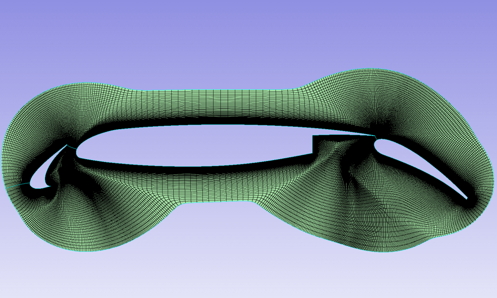
The result of the extrusion (Figure 3) used 95 extrusion steps from a first cell height of 1E-5 m, at a growth rate of 1.1.
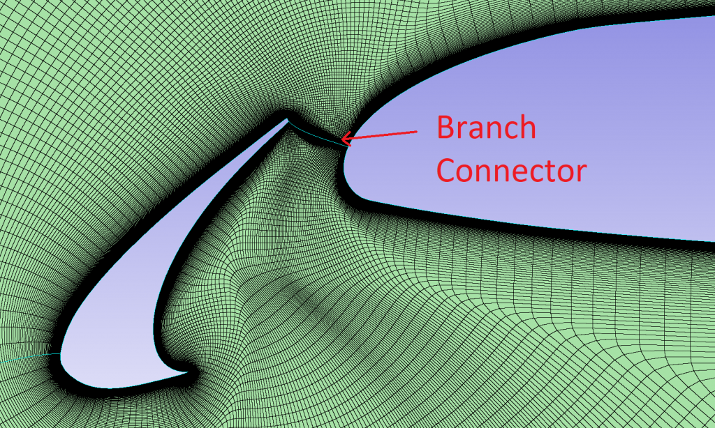
A close up of the extrusion and the “branch connector” between different airfoil elements, as shown in Figure 4. This connector allows one continuous extrusion for each separate airfoil, otherwise unconnected.
Wake Structured Domain
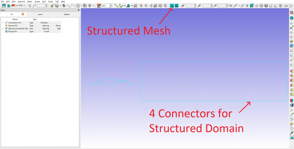
Now that a normal extrusion has been created, it is time to generate a rectangular structured domain downstream in the airfoils wake. First, make sure we have a structured mesh mode selected. Then use the four connectors in a rectangle to create a structured domain (Figure 5). Note that the number of grid points on the connectors (known as the “dimension”) needs to be equal on opposite sides of the domain.
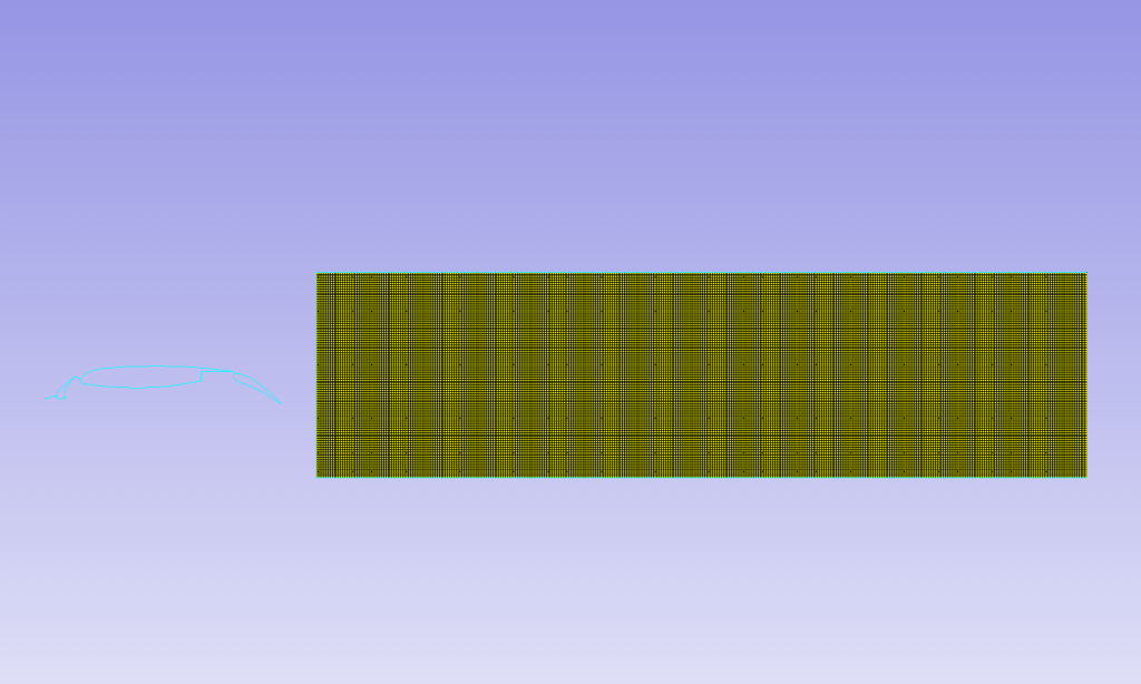
The resultant 100% structured domain, as shown in Figure 6.
Unstructured Domain
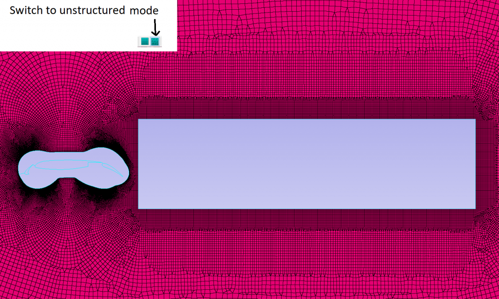
After the creation of the extrusion and structured domain, it is now time to create the unstructured rectangular farfield domain. Switching to unstructured mode on the toolbar shortcut, use “Assemble Special” for the farfield domain, including the inner edge loops. This interfaces with the two structured domains (normal extrusion and 100% structured). The resultant domain, as shown in Figure 7.
Extrusion into 3D
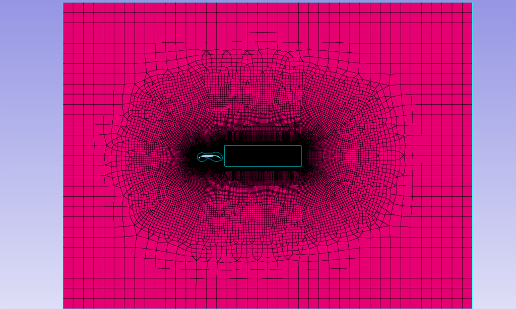
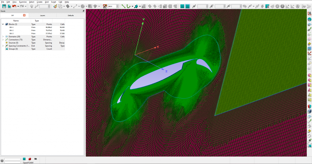
Now that we have 3 domains that form the farfield, and two inner domains for the airfoils and the wake region (Figure 8), we need to extrude the domains into 3D volume mesh.
The extrusion is very easy, and requires another extrusion, this time a “translational extrusion”. First make sure the CAE dimension mode is 3D, by going to menu and CAE->Set Dimension->3D. As Figure 9 shows, select either one the 3 domains and under the menu select Create->Extrude->Translate.
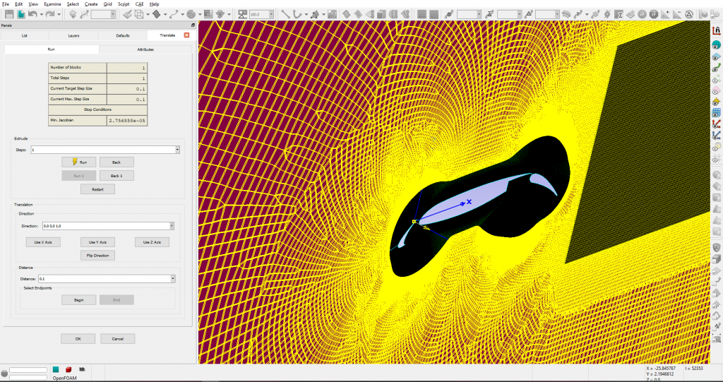
If you choose one type of domain for extrusion at a time (unstructured or structured) then you will end up with three separate “prism blocks”. As shown in Figure 10. However, if you choose all three domains in one extrusion, you will end up with one prism block. If you don’t need to access each domain as a block (e.g. for source terms), then either method will suffice.
We hope you enjoyed reading about how to generate normal extrusion hybrid meshes for multi-element airfoils.
In case you missed it, why not read about our aerospace monthly mesh blog on scripting and mesh adaption.
If you would like a free trial follow the link or checkout the further information on our website.
Thanks for reading, the next edition will be in May. Until then, stay safe with this virus around and happy meshing!
Related Posts
15.
Normal Extrusion Hybrid Meshes for Multi-Element Airfoils